8-line Olfactometer Electronics
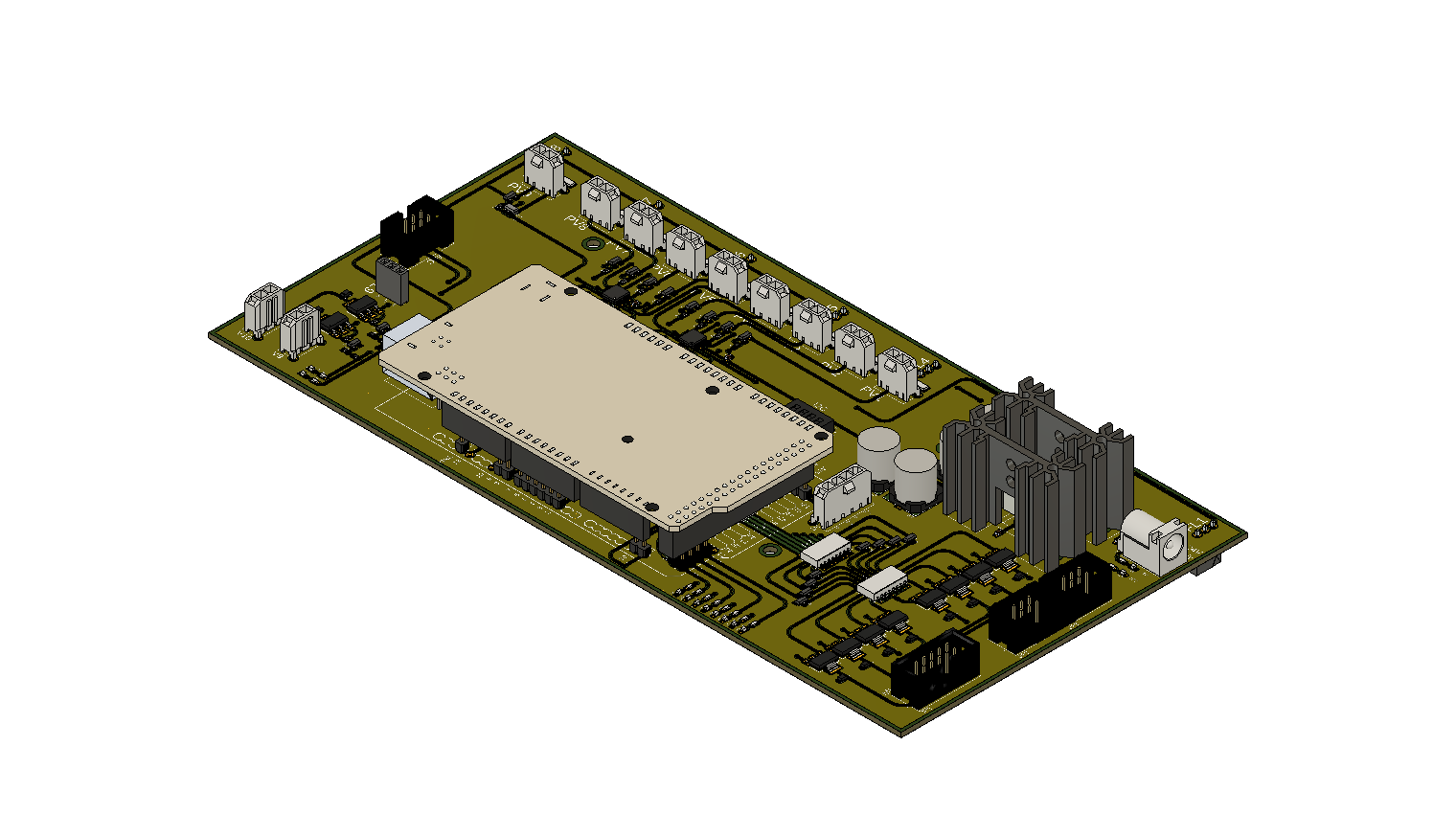
PCB Assembly
- Attach (x2) heat sinks to VR1 and VR2 using (x2) 4-40 x 1/4" screw and hex nut
- Solder Arduino header pins onto PCB
- Set I2C address on S1 (full dictionary of addresses is currently stored in master.ino source code)
- Connect master Arduino
- Make a wire to connect from J2 (4pos Molex female) to master Arduino pins (Dupont male wires). Connect to SDA, SCL, GND and GND.
- (Mount master Arduino on top using Arduino holder 3D printed part)
updates for version 2:
power:
- single 24V power supply (instead of 1x 24V supply and 1x 10V supply)
- voltage regulators & corresponding circuitry to shift down to 10V for the components that need it
- (2 voltage regulators + heat sinks to prevent overheating when multiple lines activated at once)
error fixes:
- fixes (x4) incorrectly wired proportional valves
- removes connection between isolation valves 3 & 8
other:
- multiple boards can be chained together by a single ribbon cable, which carries the power and I2C lines
- (only 1 board in the chain needs a 24V input, the rest receive power through the ribbon cable)
- updated header for connecting to mixing chamber (standard 10pos IDC cable)
new components:
- (x8) LEDs to indicate isolation valve activated
- (x2) LEDs to indicate power (10V, 24V)
- (x1) connection for additional flow sensor
- (x1) connection for additional proportional valve
- (x2) connection for additional isolation valve
- (x1) connection for Alicat MFC