Flow Sensor Calibration
To ensure accurate flow readings, each flow sensor should be individually calibrated before use.
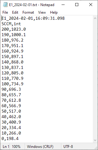
The calibration table for each flow sensor csv file contains flow rates (in SCCM) and the corresponding flow sensor value (as an integer from 0-1023).
Example calibration table:
Hardware setup
Note: With the current system, the most efficient way to calibrate new flow sensors is prior to installation onto the main manifold. Calibrating while sensors are installed on the manifold can be more time consuming (due to pressure changes when changing setpoints), so use your own discretion on which method to use (depending on how many flow sensors need to be calibrated.)
Setup options:
A. On Manifold (Flow sensor still installed on olfactometer manifold)
Recommended when calibrating 1-2 flow sensors
Example use: Recalibrating/checking calibration of currently installed flow sensors
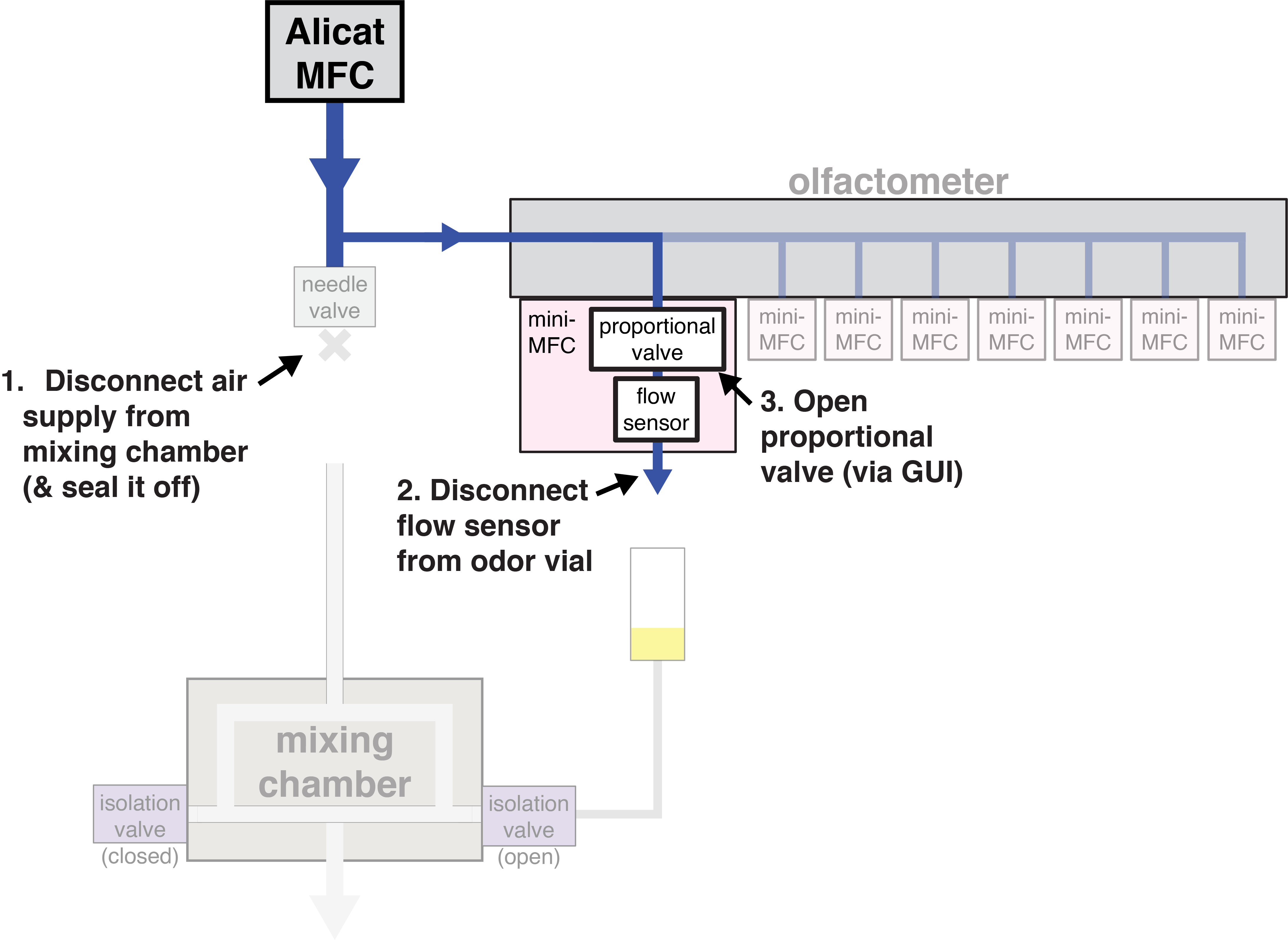
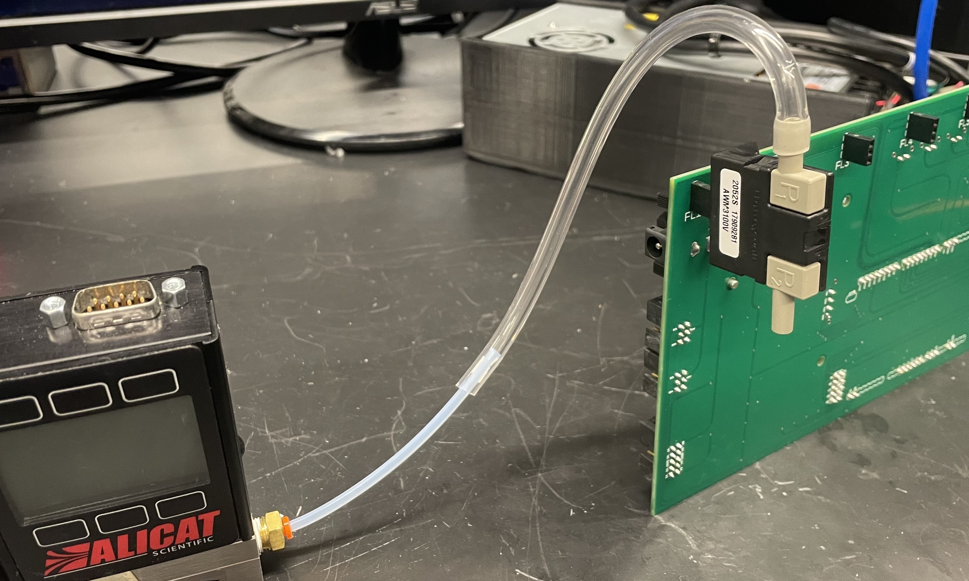
The hardware setup must be modified to ensure the entirety of the Alicat MFC output passes through the flow sensor being calibrated.
-
Disconnect the tubing that connects the Alicat MFC to the mixing chamber, and plug the open fitting. (This ensures that all air from the Alicat MFC passes through the olfactometer manifold.)
-
Disconnect the flow sensor from the odor vial. This allows the air to pass freely through the flow sensor, without anything blocking the output. (Easiest way to do this is to twist the needle, disconnecting it from the luer fitting on the flow sensor tubing.)
-
Fully open the proportional valve via the olfactometer GUI. (This, once again, ensures that all air will pass through the flow sensor.)
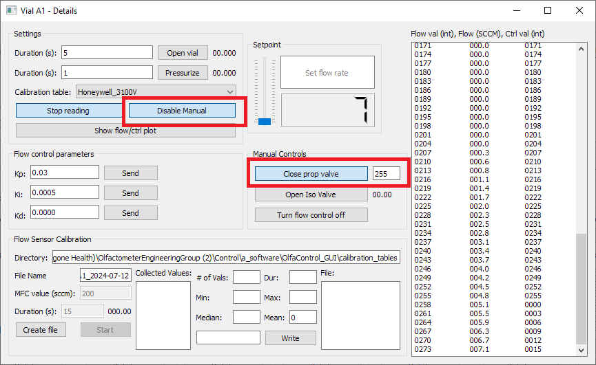
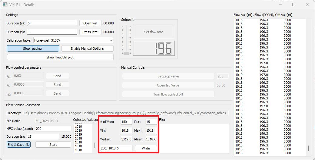
- Open the "Vial Details" popup window for the line to be calibrated.
- Select "Enable Manual Options".
- In the "Manual Controls" box, enter "255" next to the "Set prop valve" button.
- Click "Set prop valve".
B. Off Manifold
Recommended when calibrating 4+ flow sensors
Example use: New sensors that have not been installed yet
- Connect the MFC input to an air supply.
-
Connect the MFC output directly to the flow sensor input. (Flow sensor works well with 1/8" ID flexible tubing, which can be slid over 1/8" OD Teflon tubing to make a sufficiently airtight seal for this application).

-
Connect the flow sensor to the Olfactometer PCB (either directly, or using jumper wires, whichever is more convenient).

- Connect the Olfactometer PCB to the computer and 24V power supply as usual.
Software setup
Create File
- Open the Olfactometer GUI and connect to the device.
-
Open the Vial Details box for the selected flow sensor.
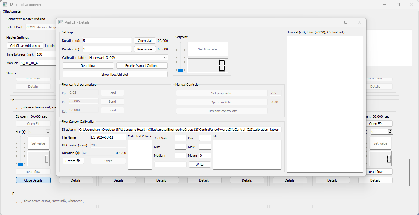
-
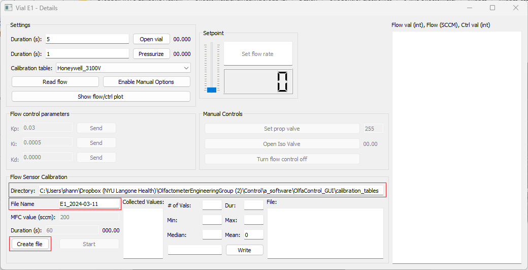
Confirm/edit the calibration table directory and enter the desired file name.
- Click "Create File". (This will create the file and set the flow sensor to "debug" mode, if it is not already.)
Calibrate
Note:* Calibration tables must* be in descending order, so it is recommended to start calibrating at the maximum capacity and work down from there. Otherwise, the table will need to be sorted manually after completing the calibration.
-
Physically set the Alicat MFC to the first desired calibration value. (Ideally, the maximum capacity of the flow sensor: 200 sccm.) Enter that same value into the "MFC value (sccm)" box.
Note: If calibrating with setup A: On Manifold, the Alicat MFC may not be able to reach 200 sccm (due to high impedance within the olfactometer manifold). If this is the case, start calibration at the highest flow rate the Alicat MFC is able to maintain in this setup (at least 120 sccm is ideal). -
Enter the desired duration of the calibration. (15 seconds is typically sufficient for off-manifold calibration, 30 seconds may be necessary for on-manifold calibration.)
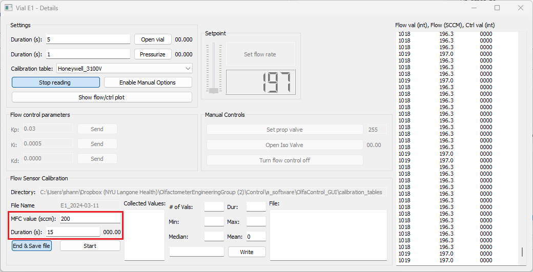
-
Click "Start".
-
Once calibration at this flow rate is complete, stats about the flow sensor data collected during that period will populate the fields in the center of the groupbox. By default, the values to write to the calibration files will display in the bottom-right box (flow rate [SCCM], mean value [integer]).
Note: Don't worry about the SCCM flow rate displayed in the "Setpoint" box - this is based on whatever calibration table is currently selected, and is likely inaccurate.
-
Check if the calibration was successful by looking at the range of values collected from the flow sensor during the calibration. If the range exceeds 4, repeated trials are recommended.
Note: Typically, at a single flow value, I run two 15-second calibrations and save the mean of the second one. If the means of the two calibrations differ by more than 1.0 on manifold or more than 0.5 off manifold, I recommend running additional 15-second calibrations until consecutive calibrations have similar values. (For setup A: On Manifold, when the Alicat MFC value is changed, the pressure within the system can take 1-2 minutes to stabilize, which affects the flow sensor readout. This setup typically requires many more consecutive trials until the system has reached stability.)
-
If the calibration was successful, click the "Write" button to write this pair to the calibration file. If necessary, you can also manually enter the values to write to the file. (Values already written to the file will be displayed in the far right box.)
-
Repeat for as many values as desired. (I typically do 10sccm increments, to save time. For more sensitive experiments, 2-5 increments may be more helpful.)
Once complete:
- Click "End & Save File"
- Go to the calibration table directory, and change the file extension from .csv to .txt. (Ignore any warnings about the file becoming unusable.)
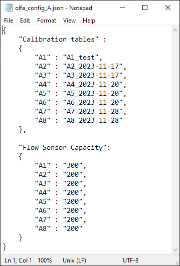
- Update the olfa_config file (using any text editor) to include the name of the new calibration table.
Example olfa_config file: